Ohm’s Law is a key theory for Electrical Engineering
One becomes an electrical engineer by learning many things in the field of electrical engineering. When a student starts learning electrical engineering, the first step is understanding a key theory known as Ohm’s Law. This law is very fundamental and is one of the most useful tools for analyzing electrical circuits, from simple circuits to very complex ones.
We may think that only Ohm’s Law is enough to analyze every electrical system. Definitely, it is not. There are many other complex laws that are applied to solve complex electrical systems. One might then ask: why do we need to study Ohm’s Law? Why not skip it and directly jump to those complex laws and theorems?
It must be clarified that those complex laws and theorems are developed with the help of Ohm’s Law. Without studying it, learning those advanced topics becomes challenging. Therefore, with this brief introduction, let us discuss why Ohm’s Law is a key theory in electrical engineering.
Who Invented Ohm’s Law?
Ohm’s Law was invented by Georg Simon Ohm, a great German physicist and mathematician, in 1827. He was born to his parents: his father, Johann Wolfgang Ohm, was a locksmith, and his mother, Maria Elizabeth Beck, was a tailor. His parents’ tremendous support helped him become a renowned scientist.
Georg Simon Ohm received his doctorate from the University of Erlangen. Dr. Ohm also worked as a teacher in many schools and published several books on mathematics.
Initially, he conducted experiments using a voltaic cell, and later with a thermocouple. A thermocouple is a device that generates electromotive force (EMF) when there is a temperature difference at its junction. He observed variations in current when additional external wires were connected to the circuit. Based on these findings, he presented his results in his book Die galvanische Kette, mathematisch bearbeitet.
Ohm’s law definition
Ohm’s law defined as
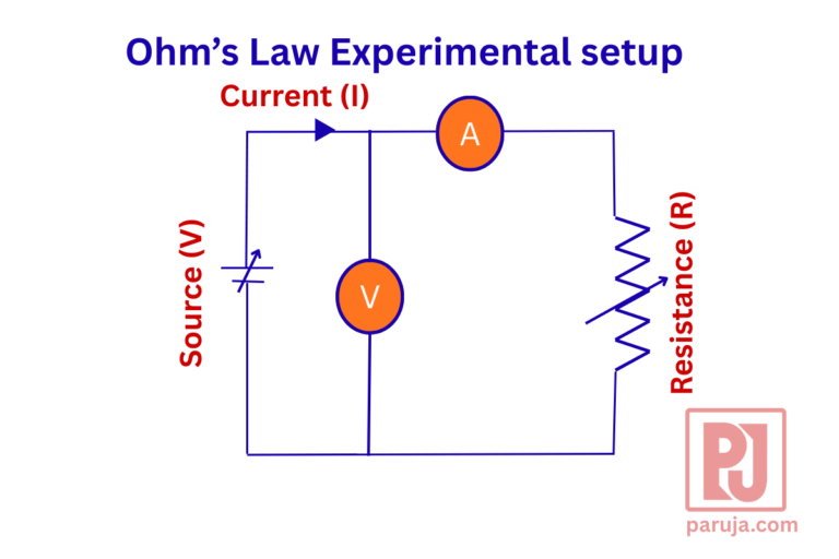
When the ambient conditions remain constant, the current flowing through a conductor is directly proportional to the applied voltage and inversely proportional to the resistance offered by the circuit.
i.e. Current (I) = Applied voltage / Resistance offered by circuit
Where:
I = Current flowing through the circuit, measured in amperes (A)
V = Applied voltage across the circuit, measured in volts (V)
R = Resistance offered by the circuit, measured in ohms (Ω)
The ohm (Ω) symbol is named after Dr. Georg Simon Ohm.

Ohm’s law observation
- As long as the applied voltage (V) in a circuit increases, the current also increases proportionally, provided other conditions remain constant.
- On the other hand, an increase in resistance causes a decrease in the current flowing through the circuit.
- If both the applied voltage and the resistance increase in the same proportion, the current remains constant.
- Since the conductivity of a current-carrying conductor changes with temperature, it is very important to keep the ambient temperature constant to obtain accurate results.
Applications of Ohm’s law
Even though Ohm’s Law is very fundamental, it is useful in the following applications in the field:
• To determine the current flowing through a circuit when a resistive load is connected, so that the appropriate conductor size can be selected accordingly.
• To determine the voltage drop across a conductor for a given amount of current flow, which helps in selecting the proper size of the conductor.
• In high-current circuits, to calculate the value of shunt resistance that must be connected across an ammeter.
• In high-voltage circuits, to determine the series resistance that must be connected with a voltmeter.
• When multiple low-voltage-rated loads are connected in series, to find the voltage drop across each load.
• Similarly, when multiple loads are connected in parallel, to calculate the current flowing through each branch of the circuit.
• Ohm’s Law is used to find current, voltage, or resistance in any electrical circuit.
Limitations of Ohm’s law
Ohm’s Law has the following limitations while analyzing electrical circuits:
• It is applicable only to pure DC circuits under constant physical conditions.
• Ohm’s Law cannot be used directly to analyze nonlinear circuits, because in such circuits the change in current is not proportional to the change in voltage. Therefore, Ohm’s Law is valid only for linear circuits.
• It is not directly applicable to AC circuits, where impedance is used instead of resistance. Impedance is a combination of resistance, inductance, and capacitance. In AC circuits, the relationship between voltage and current is not linear due to phase differences, making the direct application of Ohm’s Law difficult.
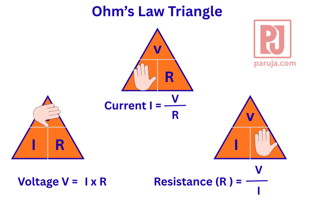
Ohm’s law Triange
t is a magical triangle used to derive current, voltage, and resistance in an electrical circuit when any two of these parameters are known. The required expression can be obtained by covering (or hiding) the parameter that needs to be found. This concept is better illustrated in the following image.
Ohm’s Law Calculator
Ohm’s Law Calculator
Enter any two values to calculate the third.
Calculations
These few calculations will help to understand about the function of ohm’s law in an electrical circuit. let us do is detail
1. An Electrical heater operated in 230 Voltage AC supply which takes 2 Ampere current through it. Find the resistance of the heater
Given:
Applied voltage : 230 V
Current flowing through heater = 2A
To find
Resistance of the heater
Solution
As per derivation of ohm’s law
Then Resistance of the heater can be derived from above equation
Applying Voltage and current in this equation
Result:
The resistance of the heater determined as 115 Ω
2. A Light decorator wants to connect his bulbs in series connection for a birthday decoration. He has 50 bulbs each with 5 watts rating with 5 volts which each bulb can maximum withstand voltage. Calculate the value of resistance need to be connected series with bulbs to ensure current within safe limits
Given:
Number of bulbs : 50
Power ratings of each bulb : 5 Watts
Maximum withstand voltage / Working voltage = 5 V
To find:
Value of Resistance to be connected in series to limit current in safe value
Solution
Let us consider it in two scenarios
Scenario-1
Actual current rating of each bulb derived from the power rating of the bulb
Let us now connect all 50 bulbs in a series connection. So total power consumption becomes
When it is connected across a 230-Voltage supply, the actual current flow will become
Scenario : 2
Now Let is derive actual resistance offered by bulb
In such case to maintain current 1 Ampere as per rating of bulb given, the resistance should be 230 Ohms. So total current will become 1 A
Hence additional resistance to be connected with circuit is
Additional resistance required = Required Resistance – Actual Resistance of the bulbs
R a = 230 – 212.96
Ra = 17.04 Ohm
Result
Additional resistance required = 17.04 Ohm