Working Principle of three phase induction motor
Three-phase induction motors are widely used in residential and commercial applications. Every electrical engineer must deal with induction motors during their work. Therefore, it is very important to understand the working principle of a three-phase induction motor before working with it.
A overview of three phase induction motor
A three-phase induction motor is fabricated with three individual windings in its stator. These stator windings are placed in the inner periphery slots of the motor. The windings are positioned at appropriate electrical angles to ensure smooth rotation of the rotor.
Inside the stator, along the motor axis, the rotor is placed. The rotor is classified into two types:
- Squirrel cage rotor
- Slip ring rotor
Squirrel Cage Rotor
In a squirrel cage rotor, copper, brass, or aluminum bars are used as rotor conductors. These rotor bars are placed on the outer periphery of the rotor. The rotor bars are short-circuited at both ends by end rings.
Slip Ring Rotor
In a slip ring induction motor, the rotor winding is similar to the stator winding. These windings are placed on the outer periphery of the rotor and are connected either in star or delta configuration. From each winding, three wires are taken out and connected to slip rings, which are mounted on the rotor shaft.
The major advantage of a slip ring rotor is that it can be connected to an external circuit for better speed, torque, and current control.
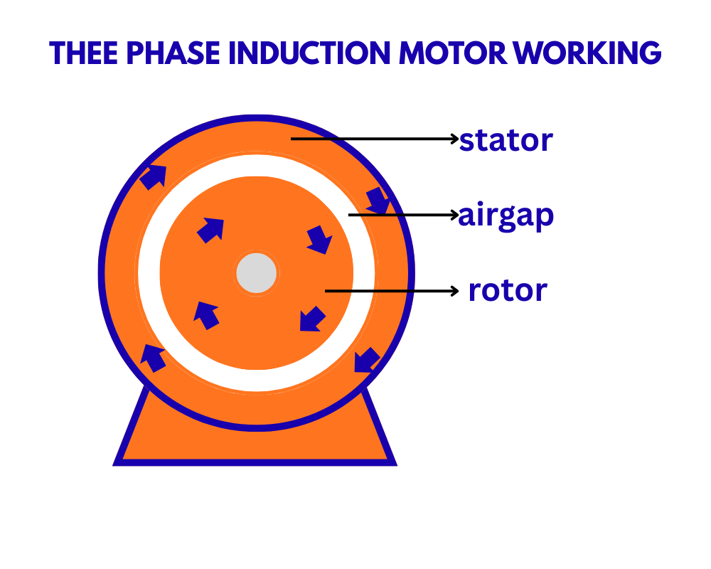
Working Principle of three phase induction motor
When a three-phase supply is connected to the stator winding, current starts flowing through the windings. This current produces an electromagnetic field.
In a three-phase supply, each phase has a 120-degree phase difference with respect to the other phases. For example, if the R phase is at zero degrees, the Y phase will be at 120 degrees, and the B phase will be at 240 degrees. Hence, the magnetic field in each phase winding reaches its maximum value according to the phase sequence.
As a result, a rotating magnetic field (RMF) is created in the stator. Since the input supply is alternating, the magnetic flux is also varying in nature. The speed at which the rotating magnetic field rotates is known as the synchronous speed.
The synchronous speed is given by:Synchronous speed (Ns)=P120f
Where:
- f = supply frequency in hertz
- P = number of poles in the stator winding
The rotating magnetic flux crosses the air gap and reaches the rotor. Initially, the rotor is in a stationary state. The magnetic flux cuts the rotor conductors, and since the rotor conductors are short-circuited, a heavy current starts flowing through the rotor winding.
According to Lenz’s law, the direction of the rotor current is such that it opposes the cause producing it, i.e., the rotating magnetic field. Due to the current flowing in the rotor winding, another magnetic field is produced by the rotor. The interaction between the stator magnetic field and the rotor magnetic field produces a force, which causes the rotor to rotate in the direction of the rotating magnetic field.
If the motor shaft is not connected to any load, the rotor should ideally rotate at the same speed as the rotating magnetic field. However, this never happens in practice because the rotor always has some load due to friction, windage, and air circulation.
Therefore, it can be concluded that the actual speed of the rotor is always less than the synchronous speed.
Important parameters of induction motor
Synchronous speed (Ns)
The speed of the rotating magnetic field when a three-phase supply is applied to the stator winding.
Actual speed (N)
The actual speed of the rotor shaft. It is always less than the synchronous speed during motoring operation.
Slip (s)
Slip is the difference between the synchronous speed and the actual rotor speed.Slip (s)=NsNs−N×100
Slip is always expressed in percentage.